
Match the system to the application.
Review systems by coolant-transfer configuration, process requirement, or industry operating conditions.
How clean coolant reaches the machine
C.R.O.S.S. supports portable coolant transfer, optional clean-coolant piping, or a combination of both. Facility layout and operating requirements determine the configuration.
| Configuration | How it works | More information |
|---|---|---|
| Clean-coolant pipingCentral | The optional CRS distributes clean coolant at 35 to 40 PSI through facility piping. C.R.O.S.S. maintains clean coolant for immediate use 24/7/365 at 99% or greater uptime. | Central → |
| No central pipingBatch | A portable unit carries dirty coolant to the system and clean coolant back, machine to machine. The configuration avoids central coolant piping and floor trenching. | Batch → |
| Mixed facilityHybrid | Use clean-coolant piping for dense cells and portable transfer for outlying machines. Both sections use one C.R.O.S.S. recycling system. | Hybrid → |
| Technical overviewCentral filtration guide | Review central coolant recycling, contaminant removal, transfer options, and system-selection factors. | The guide → |
Select equipment by process requirement
Contaminant type, required flow, fluid condition, and maintenance demand determine the appropriate equipment.
| Process | Operating requirement | More information |
|---|---|---|
| Cleanout laborSump cleaning | A manual sump cleaning that can require about four hours can be completed in approximately 15 minutes with the Green Machine. | Sump cleaning → |
| Fines & finishGrinding filtration | Ferrous swarf and abrasive grit suspended in the coolant can affect surface finish. Two-stage filtration uses magnetic separation followed by paper-bed filtration. | Grinding → |
| Oil contaminationTramp oil control | Remove free-floating, dispersed, and loosely emulsified tramp oil from machine sumps and reservoirs. Compare T1 configurations and standard T.O.S.S. models. | Tramp oil removal equipment → |
| Multiple contaminantsCoolant recycling | Shop-wide control of tramp oil, particulate, coolant concentration, new-fluid purchases, and disposal volume. Up to 85% lower new-fluid purchases and up to 90% lower disposal costs. | C.R.O.S.S. → |
| Oil-based fluidsStraight oil filtration | Straight cutting, hydraulic, quench, and EDM oils filtered to 3 microns, water to 10 ppm. Not coolant recycling. | S.O.F. → |
Sized for your plant
Industry processes, fluids, contaminants, production rates, and quality requirements influence system selection.
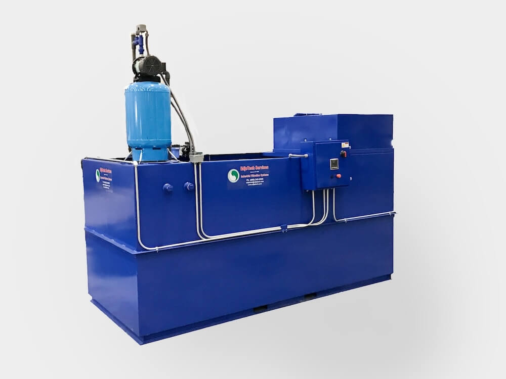 Machine shops
Contract and captive machine shops, including screw-machine, CNC machining, and grinding operations.
Machine shops →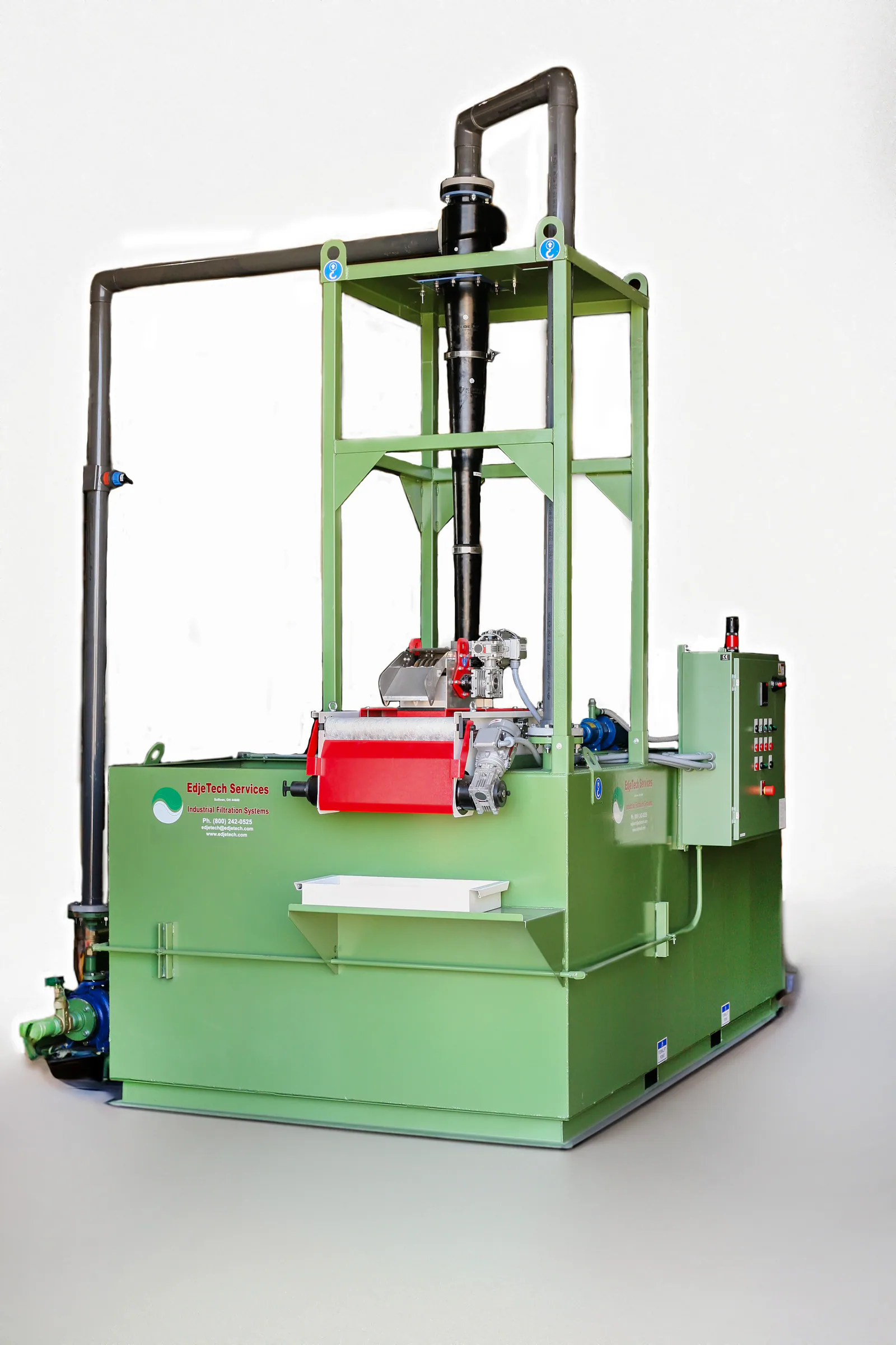 Tube mills
Real-time coolant recovery engineered around the tube or pipe mill's required flow. Systems have processed up to 990 GPM and can scale to 1,600 GPM or more.
Tube mills →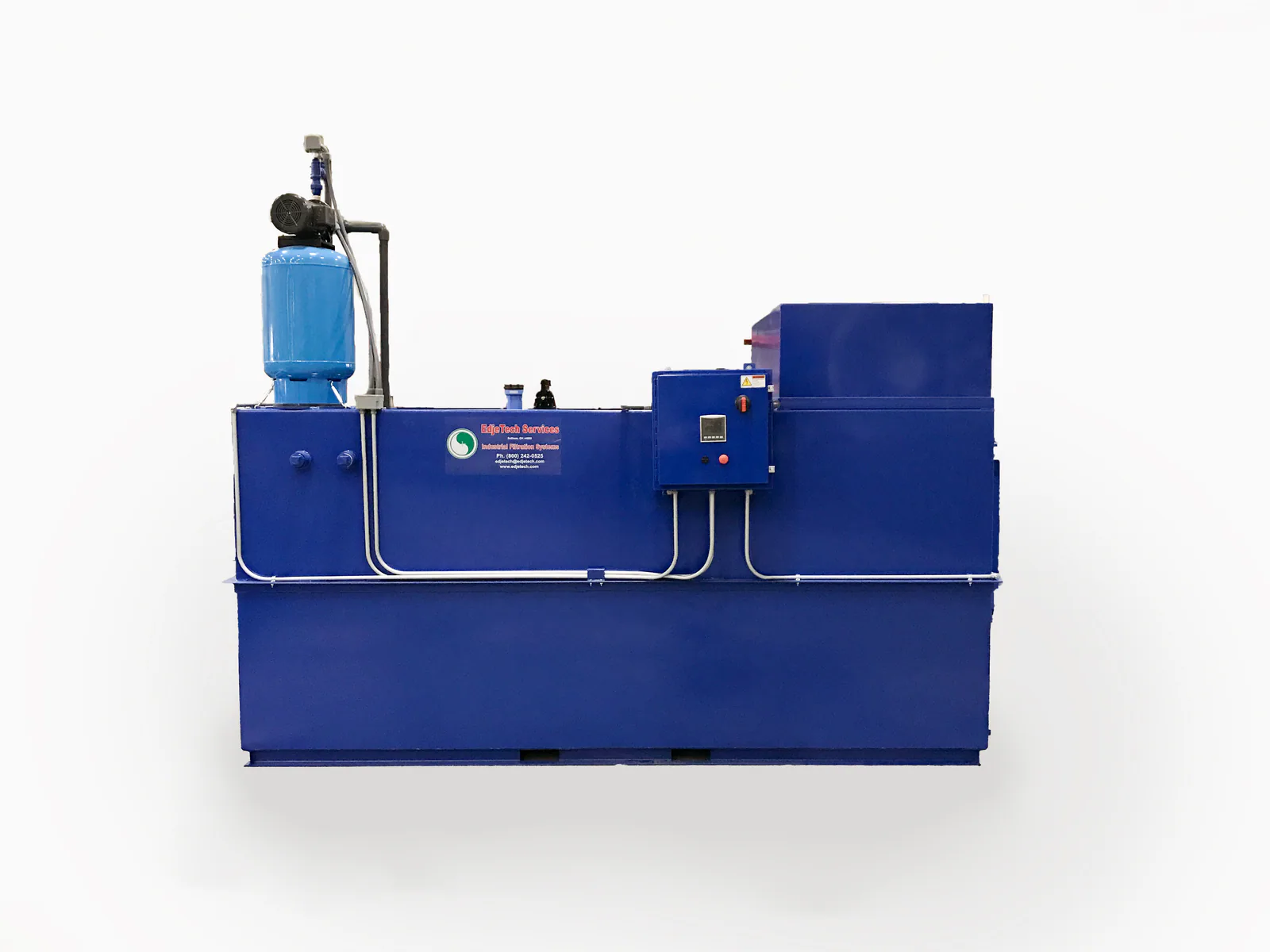 Aerospace
Titanium and nickel-alloy machining, where coolant cleanliness protects the finish spec.
Aerospace & defense →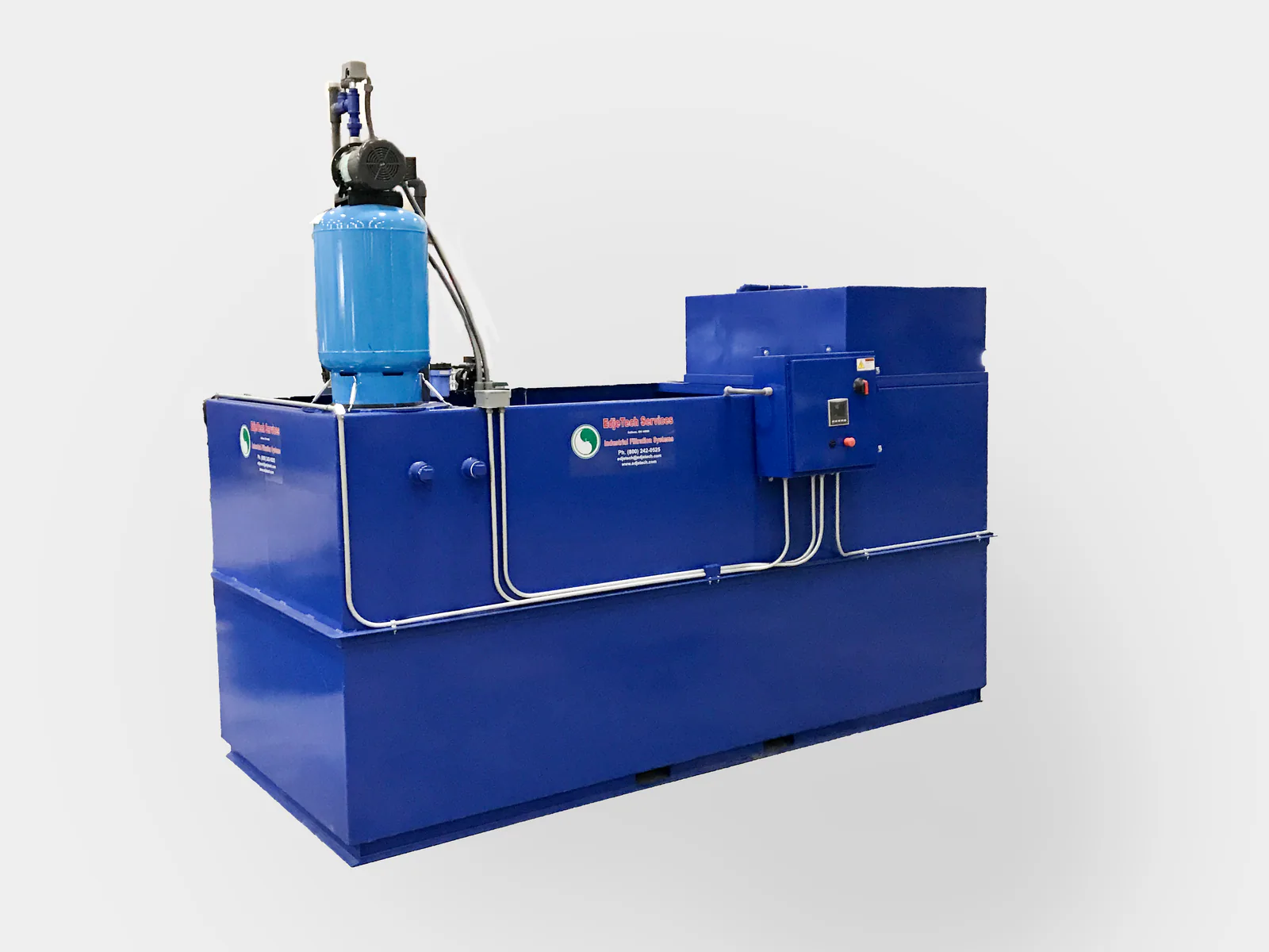 Automotive & EV
Engine and driveline components, plus EV battery housings, busbars, and motor laminations: a mixed-metal filtration problem at volume.
Automotive & EV →
Reduce time and fluid lost to contamination
Keep usable fluid in service, control contamination, and reduce the work involved in cleaning machine sumps.
- Equipment selection
C.R.O.S.S. or T.O.S.S.
Compare facility-level coolant recovery with fixed and portable reservoir treatment.
Compare equipment → - Savings and payback
Savings calculator
Estimate potential coolant, disposal, and payback results.
Estimate potential savings → - Product catalog
All products
Review the complete equipment and fluid portfolio by application.
Browse products →