
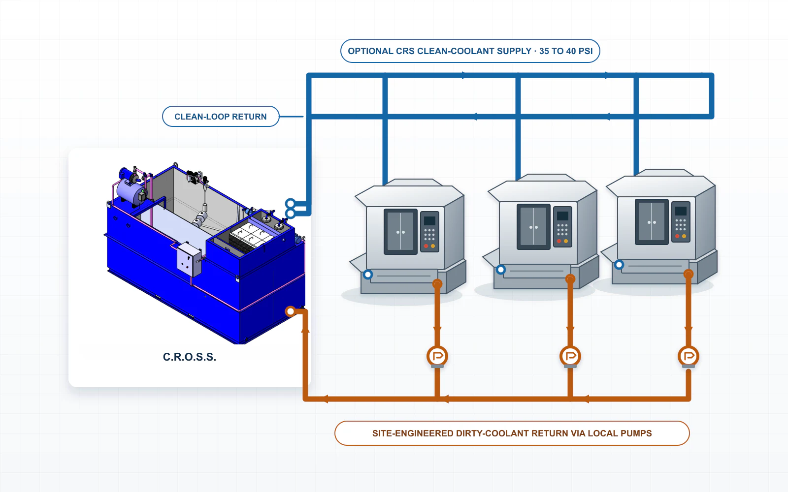
What a central coolant filtration system does
Central filtration removes selected contaminants from coolant serving multiple machines. Central recycling is the broader reuse process and can also include tramp-oil separation, concentration management, storage, makeup-fluid preparation, and return to service. A system may provide filtration without every recycling function.
Machine-side filtration treats one machine or reservoir independently. It can be the better choice when fluids or contamination differ, processes have separate cleanliness targets, or only a few reservoirs require treatment.
Core components and fluid path
A central system coordinates multiple fluid-handling stages. Depending on the application, it can combine:
- Collection and transfer: pumps, piping, trenches, portable tanks, or other methods that move dirty coolant to the treatment area.
- Bulk contaminant control: screens, baskets, settling areas, and sludge-handling provisions that keep concentrated material from overloading later stages.
- Targeted treatment: filtration and separation equipment selected for the actual solids, tramp oil, fluid chemistry, flow, and required result.
- Clean-fluid storage and return: tank capacity, pumps, valves, piping, or refill points that keep treated fluid available and move it back into service.
- Controls and safeguards: the level, flow, pressure, isolation, alarm, and overflow controls required by the configured process.
Before selecting equipment, document how coolant and removed contaminants will move, how components will be serviced, and how production will continue during downtime. Review coolant-filtration and separation approaches for machine shops for a broader equipment comparison.
Three ways to configure centralized coolant treatment
Conventional central filtration uses shared supply and return infrastructure. Centralized recycling can also use batch transfer or combine portable collection with fixed clean-coolant distribution. The practical choice depends on the building and operating workflow.
Scroll horizontally to compare all columns.
| Configuration | How fluid moves | Conditions to evaluate |
|---|---|---|
| Piped circulation | Fixed supply piping and return piping, trenches, or coolant-return channels called flumes move coolant between the machines and the central station. | Routes, elevation, chip transport, pump capacity, isolation, drain-back (coolant flowing back through the system after circulation stops), and interrupted circulation. |
| Batch transfer | Dirty coolant is collected from individual reservoirs, treated centrally, stored, and delivered for later refill. | Collection capacity, transfer labor, storage, scheduling, aisle access, and clean-container control. |
| Hybrid transfer | Dirty coolant reaches the station in batches while treated coolant is distributed through fixed piping or refill points. | Collection workflow, clean-coolant demand, distribution distance, storage, controls, and cross-contamination prevention. |
Define the configuration and treatment capacity together because transfer rate, storage capacity, and return demand can limit total system performance.
Match each treatment method to the contaminant
A central system may use one or more treatment stages. When several are required, early stages handle coarse or concentrated contamination before later equipment addresses the remaining solids or free oil.
Scroll horizontally to compare all columns.
| Method | Primary role | Operating limits |
|---|---|---|
| Screens, baskets, and settling | Intercept chips and coarse solids, then use controlled residence time for material that settles or floats. | Fine or slow-settling particles may remain. Tanks require space, cleanout access, and predictable flow. |
| Magnetic separation | Magnetic separation captures magnetically responsive ferrous particulate within the separator's effective range before it loads later filtration stages. | It does not remove aluminum, abrasive particles, or other nonmagnetic contaminants. |
| Disposable-media filtration | Capture particulate with paper, bags, cartridges, or other selected media. | Choose the media by balancing filtration grade, flow, solids loading, pressure drop, change frequency, and disposal requirements. Paper-bed filtration is one disposable-media approach. |
| Permanent-media filtration | Use reusable screens, drums, or self-cleaning elements for solids within the equipment's capture range. | Confirm separation performance, backwash requirements (reverse-flow cleaning that clears collected solids from the media), sludge handling, cleaning access, and maintenance at the required flow. |
| Density separation | Use gravity, hydrocyclones, or centrifugation where particle or phase density supports separation. | Performance depends on particle size, density difference, viscosity, flow stability, residence time, and equipment design. |
| Tramp-oil separation | Remove floating oil by skimming and separate free or mechanically dispersed droplets by settling or coalescing. | Stable chemically emulsified oil is not reliably removed by skimming, settling, or conventional coalescing. Consult the coolant supplier before selecting another treatment method. See the tramp-oil control guide. |
Arrange treatment stages by contaminant load
- Remove bulk contamination first. Keep chips, concentrated solids, and large quantities of free oil from overloading finer treatment stages.
- Use targeted separation next. Match the method to the contaminant type, critical particle-size range, required cleanliness, solids loading, and flow.
- Verify the return condition. Confirm cleanliness, concentration, temperature where relevant, storage capacity, and return flow before treated coolant goes back into service.
Factors that determine selection and sizing
System selection and sizing depend on machine count, sump volume, nominal filter rating, contaminant profile, flow, storage, and transfer requirements. The treatment equipment and fluid-handling arrangement must work as one system.
- Fluid and mixing limits: coolant manufacturer, product, approved concentration range, water quality, additives, and prohibited mixing.
- Contaminants: material, particle-size range, magnetic response, solids load, sludge, tramp oil, and process carryover (material transferred into the coolant from connected operations).
- Required result: the cleanliness and fluid condition needed by the process, tooling, pumps, nozzles, and finished part.
- Flow, volume, and storage: normal and peak demand, active fluid volume, turnover rate (how often an amount equal to that volume passes through treatment), transfer rate, return capacity, and expected growth.
- Machines, layout, and utilities: equipment served, reservoir sizes, distances, elevations, access, transfer routes, floor space, and available utilities.
- Maintenance, waste, and downtime: media, sludge and oil handling, tank cleaning, service access, backup needs, and the production effect of an interruption.
Which fluids and operations suit shared treatment?
Water-miscible coolant used in machining and grinding may be suitable for shared treatment. The machines should use the same coolant product within an approved concentration range and have similar treatment requirements. Combine different coolant products only when the fluid suppliers and system designer explicitly approve the mixture and connected processes.
Straight oils, parts-washer fluids, and other industrial process liquids need equipment and materials selected for that specific fluid. Do not combine them with water-based coolant unless the fluid suppliers and system designer approve the shared arrangement.
Representative fluid testing may be needed when separation, filter loading, oil release, or fluid compatibility is uncertain. Test representative samples from normal and difficult operating conditions, including the in-use contamination and loading the system must treat. The fluid compatibility and bottle-test guide provides an initial check for separable tramp oil.
Choosing central or machine-side treatment
Central treatment is most practical when machines use the same coolant product and need similar treatment. They must also share a workable transfer path, and the combined coolant volume and service frequency must justify shared equipment.
Scroll horizontally to compare all columns.
| Operating condition | Favors central treatment | Favors machine-side treatment |
|---|---|---|
| Fluid compatibility | Machines use the same coolant product within an approved concentration range. | Different products, additives, or required concentrations should remain separate. |
| Contamination | Contaminant types and treatment requirements are reasonably consistent across the connected operations. | One process creates contamination that should not enter a shared stream. |
| Collection and return | The building supports practical piping, batch transfer, or a hybrid arrangement. | Distance, elevation, access, or workflow makes shared transfer unnecessarily complex. |
| Operating scale | The combined coolant volume and treatment frequency justify central capacity. | Only a small number of reservoirs require treatment or their needs are intermittent and unrelated. |
| Downtime exposure | Backup capacity and service planning can limit the effect on connected machines. | A shared interruption would expose too much production without a practical backup. |
What centralization may improve
- Combine filtration, separation, storage, and monitoring in one location.
- Standardize how treated coolant is stored and returned to service.
- Use shared treatment capacity for the combined flow and contaminant load.
- Reduce duplicated fluid handling when the connected machines support one treatment approach.
These advantages depend on the shop's current fluid-handling process. Compare expected savings with current labor, fluid, waste, maintenance, and downtime costs. Shared equipment also makes several machines dependent on one treatment process, so maintenance resources and downtime plans matter.
Plan installation and ongoing maintenance
A central system changes how coolant moves through the facility and who maintains the shared equipment. Plan those responsibilities before installation.
- Document current conditions. Record coolant use, disposal, concentration history, cleaning work, filter use, downtime, and contaminant loading. Test representative fluid when treatment results are uncertain.
- Plan collection and return. Account for distance, elevation, chip transport, storage, safeguards, isolation, and machine access.
- Plan service and downtime. Determine how connected machines will operate during filter maintenance, tank cleaning, pump failure, or a planned shutdown.
- Verify startup and assign responsibility. Confirm that flow, storage, return, alarms, and controls perform as designed. Identify who will monitor the fluid, service the equipment, and maintain records and spare parts.
Include tanks and shared piping in the maintenance plan. Cleaning and treatment decisions should follow the coolant supplier's instructions and facility safety and environmental requirements.
Build the business case from the current operation
Compare the current cost of fluid handling with four cost groups: equipment and installation, consumables and maintenance, labor and waste, and production downtime. The coolant recycling ROI guide explains how to compare these costs using shop-specific inputs.
Common central coolant filtration questions
What is the difference between central filtration and central recycling?
Central filtration removes selected contaminants from coolant serving multiple machines. Central recycling is the broader reuse process and may also include tramp-oil separation, concentration management, storage, makeup-fluid preparation, and return to service.
Does every centralized treatment arrangement use a fully piped loop?
No. Centralized treatment can use fixed piping, portable batch transfer, or a hybrid of batch collection and fixed clean-coolant distribution. The building and operating workflow determine the practical layout.
Can different coolants share one central system?
A shared system normally uses one coolant product within an approved concentration range. Combine different products only when the fluid suppliers and system designer explicitly approve the mixture and every connected process.
How is central-system flow sized?
Flow sizing accounts for normal and peak demand, active fluid volume, required turnover, contaminant loading, treatment contact time (how long coolant remains in a treatment stage), batch-delivery rate, storage, return capacity, future growth, and capacity during service.
Will filtration restore severely degraded coolant?
Filtration removes only the contaminants it is designed to capture. Restoring coolant is part of the broader recycling process and may also require supplier-approved chemistry correction. Some severely degraded coolant cannot be recovered. Depleted additives, stable chemically emulsified oil, incompatible contamination, or major chemical changes may require replacement. Representative testing and fluid-supplier guidance may be necessary.